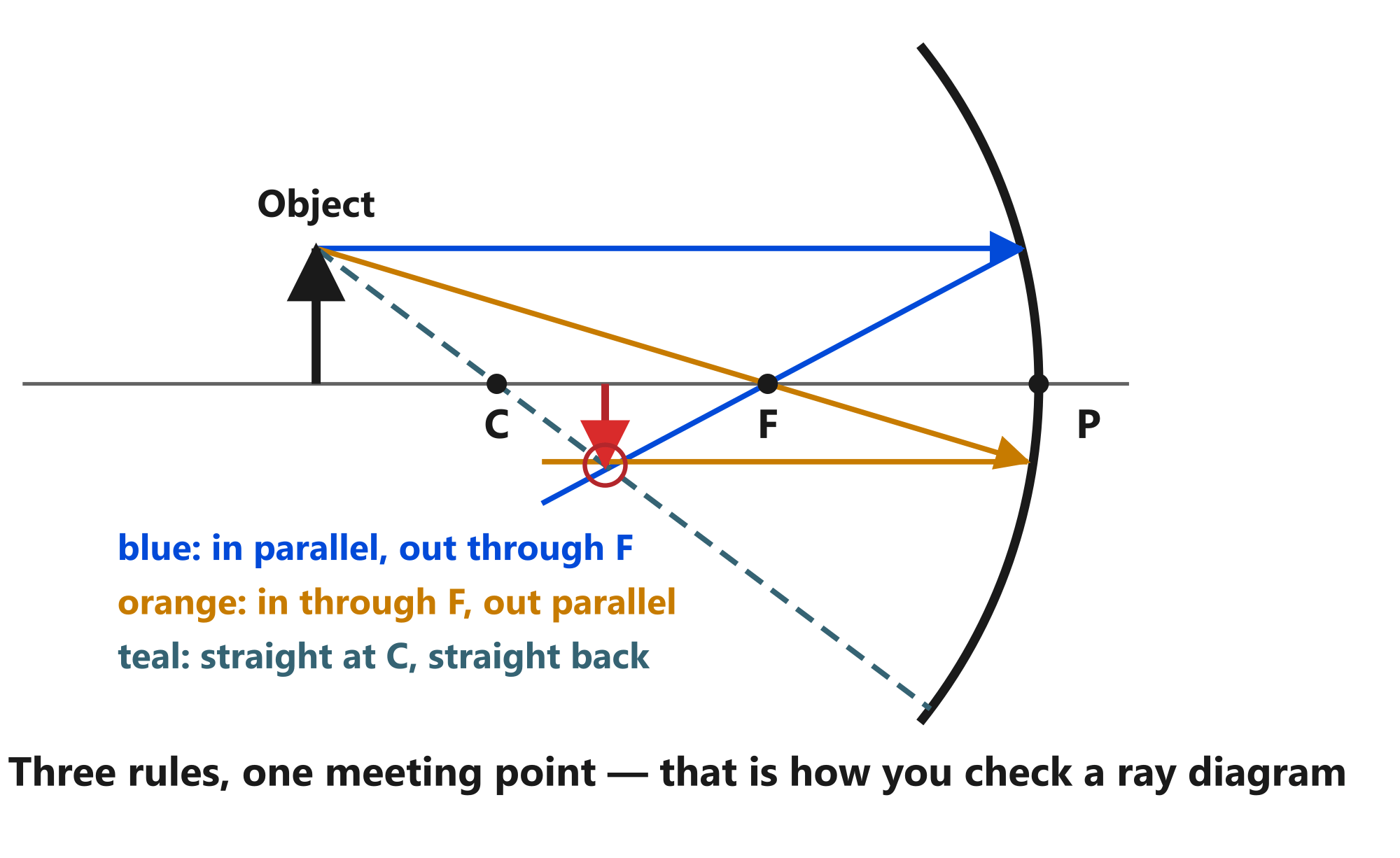
A concave mirror ray diagram is a drawing that shows how light from an object reflects off the mirror to form an image. It uses straight lines with arrows to represent the path of light rays. Drawing one takes four steps: set up the mirror and key points, choose two incident rays from the object, reflect them using the two standard rules, and mark where the reflected rays meet. Here is the step-by-step method for drawing ray diagrams for both concave and convex mirrors, with worked examples for every object position.
A concave mirror ray diagram is like a treasure map for light. The object marks where the treasure starts, the mirror is the obstacle the light bounces off, and the image is the spot the light reaches. Just as you need two landmarks to find your position on a map, you need two light rays to locate an image.
Before you start: the parts of a concave mirror ray diagram
You need five reference points and one tool before you draw anything:
- Principal axis (PA): a straight horizontal line through the centre of the mirror.
- Pole (P): the centre point of the mirror surface, on the principal axis.
- Centre of curvature (C): the centre of the imaginary sphere from which the mirror is cut. For a concave mirror, C is in front. For a convex mirror, C is behind.
- Focal point (F): the point where parallel rays converge (concave) or appear to diverge from (convex). It lies halfway between P and C: f = R/2.
- Object: drawn as a vertical arrow on the principal axis. The arrow's tip is the reference point for ray tracing.
- Straight edge (ruler): essential for accurate rays. Freehand diagrams invite errors.
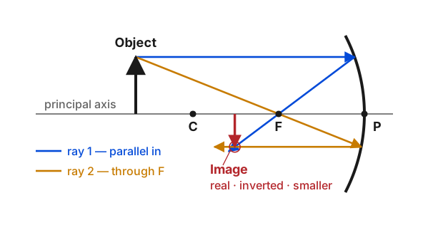
The two essential rules for concave mirror ray diagrams
Every concave mirror ray diagram uses these two rules. They come directly from the law of reflection applied to a curved surface:
Rule 1 — Parallel ray: A ray travelling parallel to the principal axis reflects through the focal point F.
Rule 2 — Focus ray: A ray passing through the focal point F on its way to the mirror reflects parallel to the principal axis.
You can also use two optional rules to check your work:
Rule 3 — Centre ray: A ray passing through the centre of curvature C hits the mirror along the normal (perpendicular to the surface) and reflects straight back along the same path.
Rule 4 — Pole ray: A ray striking the pole at any angle reflects at the same angle on the other side of the principal axis (law of reflection).
For a basic concave mirror ray diagram you only need Rules 1 and 2. Rules 3 and 4 are for verification — if all four reflected rays meet at the same point, your concave mirror ray diagram is correct.
Step-by-step method for any concave mirror ray diagram
The method is the same for every object position. Only the locations of the image change. Here is the four-step process:
Step 1: Set up the mirror, axis, and key points. Draw a concave mirror as a curved line with the reflecting side facing left. Light comes from the left. Draw the principal axis as a horizontal line through the centre of the mirror. Mark P at the centre of the mirror, C at a measured distance in front, and F halfway between P and C. Place the object (a vertical arrow) on the principal axis at the chosen position.
Step 2: Draw two incident rays from the top of the object. Pick the top of the object arrow. Use a ruler to draw:
- One ray from the top of the object straight toward the mirror, parallel to the principal axis (the parallel ray).
- A second ray from the top of the object passing through F on its way to the mirror (the focus ray).
Draw arrows on each ray pointing toward the mirror.
Step 3: Reflect both rays. Where each ray hits the mirror, follow the rules:
- The parallel ray reflects through F. Use a ruler to draw a line from the point of incidence through F, continuing past it.
- The focus ray reflects parallel to the principal axis. Use a ruler to draw a line from the point of incidence straight right, parallel to the principal axis.
Draw arrows on each reflected ray pointing away from the mirror.
Step 4: Mark the image. The reflected rays intersect at a point in front of the mirror. That point is the image of the top of the object. Draw the image as a vertical arrow from the principal axis up to the intersection point.
If the reflected rays diverge instead of meeting (what happens when the object is between F and P), extend them behind the mirror with dashed lines. Where the dashed lines meet is the virtual image.
Concave mirror ray diagram for all object positions
Here is how the four-step method plays out for each of the six object positions. The reflected rays from Rules 1 and 2 always determine the image; the table below describes where they meet and what kind of image they produce.
Object at infinity. The rays arrive perfectly parallel. They converge at F after reflection. The image is a point, real and inverted, at the focus.
Object beyond C. The object is farther than the centre of curvature. The image forms between C and F. It is real, inverted, and diminished. This is the standard setup for a telescope mirror collecting starlight.
Object at C. The object sits exactly at the centre of curvature. The image forms at C as well. It is real, inverted, and the same size as the object.
Object between C and F. The object is between the centre of curvature and the focus. The image forms beyond C. It is real, inverted, and magnified. This is how a projector works.
Object at F. The object sits exactly at the focus. The reflected rays emerge parallel and never meet. The image is at infinity — infinitely large, real, and inverted.
Object between F and P. The object is between the focus and the pole. The reflected rays diverge. Trace them backward behind the mirror with dashed lines — they meet behind the mirror. The image is virtual, upright, and magnified. This is how a shaving mirror works.
| Object Position | Image Position | Image Size | Image Nature |
|---|---|---|---|
| At infinity | At F | Point-sized | Real, inverted |
| Beyond C | Between C and F | Diminished | Real, inverted |
| At C | At C | Same size | Real, inverted |
| Between C and F | Beyond C | Magnified | Real, inverted |
| At F | At infinity | Highly magnified | Real, inverted |
| Between F and P | Behind mirror | Magnified | Virtual, upright |
For a more detailed discussion of each case, see the complete guide on concave mirrors. For a direct comparison between the two mirror types, see concave vs convex mirror.
How to draw a convex mirror ray diagram
A convex mirror ray diagram follows the same four-step structure as a concave mirror ray diagram, but with two important differences: the focal point F and centre of curvature C are behind the mirror, and the reflected rays always diverge.
The two rules for convex mirrors:
Rule 1 — Parallel ray: A ray travelling parallel to the principal axis reflects so that its extension passes through F behind the mirror.
Rule 2 — Focus ray: A ray directed toward F (behind the mirror) reflects parallel to the principal axis.
The four steps:
Step 1: Set up. Draw a convex mirror as a curved line with the reflecting side facing left (bulging toward the incoming light). Draw the principal axis. Mark P at the centre of the mirror. Mark F and C behind the mirror (dashed or behind the surface). Place the object as a vertical arrow in front.
Step 2: Draw incident rays. From the top of the object:
- Draw one ray parallel to the principal axis toward the mirror.
- Draw a second ray directed toward F behind the mirror.
Step 3: Reflect. The parallel ray reflects as if it came from F — draw the reflected ray diverging from the mirror surface, and extend it behind the mirror with a dashed line through F. The ray aimed at F reflects parallel to the principal axis — draw the reflected ray horizontally from the mirror, and extend it behind the mirror with a dashed line parallel to the axis.
Step 4: Mark the image. The dashed extensions of the two reflected rays meet behind the mirror, between P and F. The image is virtual, upright, and diminished. It is always between P and F regardless of the object's position.
For a convex mirror, there are only two meaningful object positions (at infinity and between infinity and P), and both produce the same type of image — virtual, upright, and diminished. For the full treatment, see the guide on convex mirrors.
Common mistakes in mirror ray diagrams
Mistake 1: Getting F and C in the wrong place. The most common error in a concave mirror ray diagram is putting F and C in the wrong positions. For a concave mirror, F is halfway between P and C, and both are in front. For a convex mirror, both are behind. Many students draw F and C in front for convex mirrors out of habit. Label each point clearly before you draw any rays.
Mistake 2: Drawing the reflected ray through F for any ray. Rule 1 only works for rays that start parallel to the principal axis. A random ray does not automatically reflect through F. Only the parallel ray goes through F after reflection.
Mistake 3: Forgetting arrowheads. Light travels from the object to the mirror and then from the mirror to the image (or to the eye). Every ray must have an arrowhead showing its direction. Without them the diagram is ambiguous.
Mistake 4: Using solid lines for virtual extensions. Virtual rays — the parts behind the mirror where light does not actually travel — must be dashed or dotted. Solid lines suggest real light paths and confuse the image type.
Mistake 5: Placing the object below the principal axis. Standard practice is to place the bottom of the object on the principal axis. This makes the image location straightforward: the bottom of the image also lies on the principal axis, so you only need to find the top of the image.
Mistake 6: Drawing only one ray. One ray gives you a line but not a point. You need at least two reflected rays to find where they intersect. A third ray confirms your result.
Mistake 7: Estimating instead of using a ruler. Ray diagrams depend on geometry. A slight freehand curve or a casually placed focal point shifts the image location. Use a ruler and measure distances when possible.
How to verify your ray diagram is correct
Here is a three-check method for any concave mirror ray diagram:
-
The intersection test: All reflected rays from the same object point should meet at a single image point. If your two reflected rays meet but a third does not, check which ray was drawn incorrectly.
-
The sign test: For a concave mirror, a real image forms in front of the mirror (v is negative by the Cartesian sign convention). A virtual image forms behind (v is positive). Check that your diagram matches the sign convention.
-
The mirror formula test: Use 1/f = 1/u + 1/v to calculate the image distance from your object distance and focal length. Your diagrammed image distance should approximately match the calculated value. Exact alignment is rare with hand-drawn diagrams; close agreement is sufficient.
The Physics Classroom ray diagrams tutorial provides step-by-step guidance with interactive practice for both concave and convex mirrors. For a deeper look at the mirror formula and sign convention, see Hyperphysics mirror ray tracing.
Practice checklist
Before you call your concave mirror ray diagram complete, confirm each item:
- Mirror shape correct (concave curves in, convex curves out)
- Principal axis drawn as a straight horizontal line
- P, F, and C labelled with correct positions (F and C in front for concave, behind for convex)
- Object is a vertical arrow with its base on the principal axis
- At least two incident rays from the top of the object
- Ray arrows point toward the mirror (incident) and away (reflected)
- Parallel ray reflects through F (concave) or extends through F (convex)
- Focus ray reflects parallel to principal axis
- Dashed lines for virtual rays only (behind the mirror)
- Solid lines for real rays (in front of the mirror)
- Image drawn as a vertical arrow at the intersection point
- Image labelled as real or virtual, inverted or upright
Summary
A concave mirror ray diagram shows where an image forms when light from an object reflects off a spherical mirror. The method for drawing a concave mirror ray diagram is the same for both types: set up the mirror and axis, draw two incident rays from the top of the object (one parallel to the principal axis, one through or toward F), reflect them using the two standard rules, and mark where they meet. For concave mirrors the reflected rays converge in front to form real images (or diverge for virtual images when the object is inside F). For convex mirrors the reflected rays always diverge, and the image is found by extending them behind the mirror. Avoid the seven common mistakes above, use the checklist to verify your work, and you will draw accurate ray diagrams every time.
For how mirrors compare with lenses, read our lens vs mirror comparison guide. For the underlying physics of how light reflects, see the guide on reflection of light examples.
Frequently Asked Questions
What is a ray diagram for a concave mirror?
A ray diagram for a concave mirror is a drawing that shows how light from an object reflects off the mirror to form an image. You draw at least two incident rays from a point on the object, reflect them using the rules for concave mirrors, and find where the reflected rays intersect. That intersection point is the image location.
How many rays do you need for a concave mirror ray diagram?
You need at least two rays to locate an image. Two straight lines intersect at a single point, so two reflected rays are sufficient to find the image location. Drawing a third ray is a good way to check your work — all reflected rays should meet at the same point if the diagram is correct.
What are the rules for drawing a concave mirror ray diagram?
The two essential rules are: (1) A ray parallel to the principal axis reflects through the focal point F. (2) A ray through the focal point F reflects parallel to the principal axis. Additional useful rays include the centre ray (through C reflects back on itself) and the pole ray (strikes the pole and reflects at an equal angle).
What are common mistakes in mirror ray diagrams?
The most common mistakes are: drawing the reflected ray through F for a ray that was not parallel to the principal axis, placing the object below the principal axis, drawing rays that do not follow the law of reflection at the mirror surface, confusing the focal point with the centre of curvature, and using dashed lines for real rays instead of virtual extensions.
How do you draw a ray diagram for a convex mirror?
For a convex mirror, use two rules: (1) A ray parallel to the principal axis reflects so its extension passes through the focal point F behind the mirror. (2) A ray directed toward F behind the mirror reflects parallel to the principal axis. The reflected rays diverge, so you extend them behind the mirror with dashed lines. The intersection of the extensions is the virtual image location.
What is the difference between a concave and convex mirror ray diagram?
In a concave mirror ray diagram, the reflected rays converge in front of the mirror and actually intersect, forming a real image that can be projected on a screen. In a convex mirror ray diagram, the reflected rays diverge and never meet in front; you must extend them behind the mirror with dashed lines to find their virtual intersection. The image is always virtual, upright, and diminished for a convex mirror.

About Umar Farooq
Umar Farooq writes in-depth guides on the physics of light and optics — from reflection, refraction, and lenses to diffraction, lasers, and fiber optics, explained from first principles.
Read more about Umar Farooq →