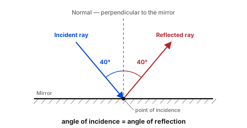
Here is how to draw a diagram of reflection in 3 simple steps. A diagram of reflection shows what happens when light bounces off a surface. You draw the surface, the normal line, the incoming ray, and the outgoing ray — then you label the angles. The whole thing follows one rule: the angle of incidence equals the angle of reflection.
Picture throwing a ball at a flat wall. The ball hits the wall and bounces back at the same angle you threw it. A diagram of reflection captures that same idea on paper. Only instead of a ball and a wall, you draw rays and a mirror.
The essential parts of a diagram of reflection
Before you start drawing, you need to know what every diagram of reflection includes. These are the standard labelled parts:
| Part | What it is | How you draw it |
|---|---|---|
| Reflecting surface | The mirror or boundary | A straight horizontal line |
| Normal line | Perpendicular reference line | A dashed line at 90° to the surface |
| Incident ray | Light approaching the surface | A straight line with an arrow pointing toward the surface |
| Reflected ray | Light leaving the surface | A straight line with an arrow pointing away from the surface |
| Angle of incidence | Angle between incident ray and normal | A curved arc labelled i |
| Angle of reflection | Angle between reflected ray and normal | A curved arc labelled r |
Every diagram of reflection uses these six components. The Physics Classroom explains that the same parts apply whether you are drawing for a plane mirror, a curved mirror, or even a water surface.
Step 1: Draw the surface and the normal line
Draw a straight horizontal line for the reflecting surface. This represents your mirror or boundary. Then choose a point on this line where the light will strike — this is the point of incidence (often labelled O).
At this point, draw a normal line. The normal is a dashed line perpendicular to the surface. If your surface is horizontal, the normal is vertical. Use a protractor or set square to make sure it is exactly 90°.
The normal is the most important part of any diagram of reflection. It is your reference for measuring both angles. Without a correct normal, your diagram will be wrong. Many beginners skip this step or draw the normal at the wrong angle — and their entire diagram of reflection ends up inaccurate as a result.
Step 2: Draw the incident ray
From the top left (or wherever your light source is), draw a straight line ending at the point of incidence. This is the incident ray. Add an arrowhead on the ray pointing toward the surface to show direction. Use a ruler and pencil so you can erase and correct if needed.
Now measure the angle between the incident ray and the normal. This is the angle of incidence. Mark it with a small curved arc and label it i (or θᵢ). A typical angle for practice diagrams is 30° or 45°. A reflection of light diagram for a plane mirror usually uses an angle between 20° and 60° for the clearest result.
Step 3: Draw and label the reflected ray
Here is where the law of reflection does its work. The angle of reflection must equal the angle of incidence. Measure the same angle on the other side of the normal and draw a straight line from the point of incidence outward. This is the reflected ray. Add an arrowhead pointing away from the surface. The incident and reflected rays should be on opposite sides of the normal and in the same plane.
Label the reflected ray and mark the angle of reflection with a curved arc labelled r (or θᵣ). The Science Learning Hub notes that this simple equality — angle in equals angle out — is the single rule that governs all reflection, from mirrors to lakes to radar. Every reflection diagram, no matter how complex, builds on this one principle.

Special case 1: Plane mirror image diagrams
When you draw a diagram of reflection for a plane mirror image, you add extra steps. The goal is to show where the image appears and how the observer sees it.
- Draw the object — usually an upright arrow in front of the mirror.
- Locate the image — measure the object's distance from the mirror and mark the image the same distance behind the mirror. Draw it as a dashed arrow.
- Draw sight lines — from the observer's eye to the image (dashed behind the mirror, solid from mirror to eye).
- Draw the incident rays — from the object to the points where the sight lines meet the mirror.
- Check the angles — the angle of incidence must equal the angle of reflection at each point.
The image in a plane mirror is always the same size as the object, upright, reversed left-to-right, and the same distance behind the mirror as the object is in front.
Special case 2: Diffuse vs specular reflection diagrams
To draw a diagram comparing diffuse and specular reflection, draw two side-by-side setups:
Specular reflection (smooth surface): Draw three parallel incident rays hitting a flat horizontal surface. The normal is the same for all rays (straight vertical), so all reflected rays are also parallel. Label this "regular reflection" or "specular reflection."
Diffuse reflection (rough surface): Draw the same three parallel incident rays hitting an uneven surface. Draw bumps on the surface to show roughness. Each ray hits at a different point with a different normal direction. The reflected rays scatter in many directions. Label this "diffuse reflection."
This side-by-side reflection diagram is one of the most common homework questions in secondary school physics. It explains why a mirror gives a clear image but a brick wall does not. The law of reflection holds at every individual point in both cases — it is the surface roughness that changes the outcome, not the physics. A reflection of light diagram showing both types side by side is the clearest way to teach this concept.
Special case 3: Concave mirror diagrams
Curved mirrors follow the same law of reflection, but the normal changes direction across the surface. For a concave mirror, use these ray rules:
- A ray parallel to the principal axis reflects through the focal point (F).
- A ray through the focal point reflects parallel to the principal axis.
- A ray through the centre of curvature (C) reflects back on itself.
The image can be real or virtual depending on where the object sits. If the object is beyond C, the image is real, inverted, and smaller. If the object is between F and the mirror, the image is virtual, upright, and larger. The common idea that "concave always magnifies" is wrong — see the note below.
Common mistakes in diagrams of reflection
Mistake 1: Measuring angles from the surface. Students often measure the angle between the ray and the mirror. But the angle of incidence is measured from the normal, not the surface. If a ray comes in at 30° to the mirror, the angle of incidence is 60°. This is the single most common error in student diagrams of reflection.
Mistake 2: Forgetting arrowheads. Every ray must have an arrowhead showing direction. Incident rays point toward the surface. Reflected rays point away. An unarrowed line is not a ray — it is just a line.
Mistake 3: Assuming concave always magnifies. Whether a concave mirror magnifies or shrinks the image depends on the object's distance from the focal point. Place the object close (within one focal length) and the image is larger. Place it far (beyond C) and the image is smaller and inverted. For more on how reflection compares to other light behaviours, see reflection vs refraction.
Mistake 4: Drawing curved mirror normals wrong. For a curved mirror, the normal at each point is a line from that point through the centre of curvature. Take the time to draw it correctly — your diagram will be accurate or wrong based on this line.
Summary
A diagram of reflection needs only the surface, the normal, the incident ray, and the reflected ray — with the angles equal. Once you master that for a flat surface, the same principle extends to plane mirror images, curved mirrors, and diffuse reflection. The Evident Scientific guide to reflection offers more examples of how these diagrams apply in real optical systems. For more on reflection fundamentals, see the reflection physics waves pillar guide and real-world reflection of light examples.
Frequently Asked Questions
How do you draw a diagram of reflection of light?
To draw a diagram of reflection of light, start by drawing the reflecting surface (usually a straight line for a plane mirror). Draw a normal line perpendicular to the surface at the point of incidence. Then draw the incident ray approaching the surface at an angle. Measure the angle of incidence from the normal, and draw the reflected ray at the same angle on the other side of the normal. Label the incident ray, reflected ray, normal, angle of incidence, and angle of reflection.
What are the parts of a reflection diagram?
A reflection diagram includes the reflecting surface, the normal line (a dashed line perpendicular to the surface at the point of incidence), the incident ray (approaching the surface), the reflected ray (leaving the surface), the angle of incidence (between incident ray and normal), and the angle of reflection (between reflected ray and normal). These are the standard labelled parts of a diagram of reflection.
What is the law of reflection in diagrams?
The law of reflection states that the angle of incidence equals the angle of reflection. In a diagram of reflection, both angles are measured from the normal line, not from the surface. The incident ray, reflected ray, and normal all lie in the same plane. This law applies whether the surface is flat or curved — only the normal direction changes.
What is the difference between a ray diagram and a reflection diagram?
A ray diagram is a general physics tool that traces the path of light using straight lines with arrows. A reflection diagram is a specific type of ray diagram that shows how light bounces off a surface. Both use the same conventions: straight lines for rays, arrowheads for direction, and angles measured from the normal.
How do you draw a reflection diagram for a curved mirror?
For a curved mirror, draw the principal axis as a horizontal line through the centre of the mirror. Mark the focal point (F) and centre of curvature (C). Follow ray rules: a ray parallel to the principal axis reflects through the focal point; a ray through the focal point reflects parallel to the principal axis. The image forms where the reflected rays intersect.
What is the normal in a reflection diagram?
The normal is a dashed line drawn perpendicular to the reflecting surface at the point where the incident ray strikes. It is the reference line from which both the angle of incidence and angle of reflection are measured. The normal is not a light ray — it is a construction line that helps you apply the law of reflection correctly.

About Umar Farooq
Umar Farooq writes in-depth guides on the physics of light and optics — from reflection, refraction, and lenses to diffraction, lasers, and fiber optics, explained from first principles.
Read more about Umar Farooq →