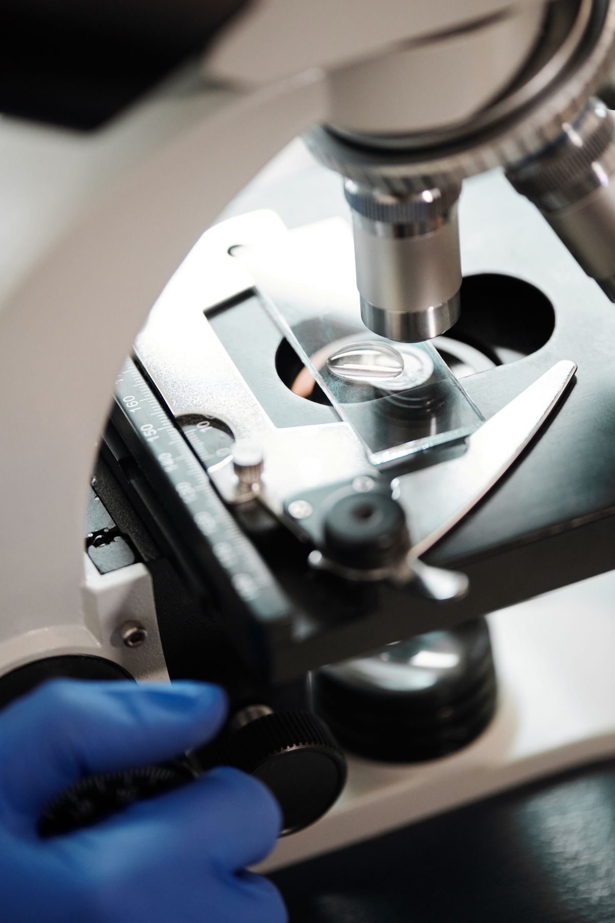
Polarized light microscopy uses two crossed polarising filters to reveal hidden structures in materials that are invisible under ordinary light. It works because certain materials — crystals, minerals, polymers — split light into two components that travel at different speeds. A polariser below the specimen ensures the illuminating light vibrates in one direction only. An analyser above the specimen, oriented at 90° to the polariser, blocks all light except what has been altered by the specimen. The result: striking interference colours and contrast that map the specimen's internal structure.
Picture a picket fence with vertical slats. A rope shaken up and down passes through freely; shaken sideways, it slams against the slats and stops. Now imagine two such fences, one vertical and one horizontal, with a birefringent crystal sitting between them. The first fence (polariser) lets only vertical wiggles through. The crystal splits the wiggle into a vertical component and a horizontal component. The horizontal component makes it past the second fence (analyser), while the vertical one is blocked. What you see is the interference pattern of those two recombined components — colour and brightness that tell you about the crystal's structure.
This core idea — two crossed polarisers with a birefringent sample between them — is the entire foundation of polarized light microscopy.
What is polarized light microscopy?
Polarized light microscopy is a contrast-enhancing optical technique that exploits the interaction between plane-polarised light and anisotropic (birefringent) materials. It requires two polarising elements: a polariser between the light source and the specimen, and an analyser between the objective and the eyepiece or camera. When the polariser and analyser are oriented with their transmission axes at 90° — a configuration called crossed polarisers — no light passes through in the absence of a specimen. The field of view appears dark.
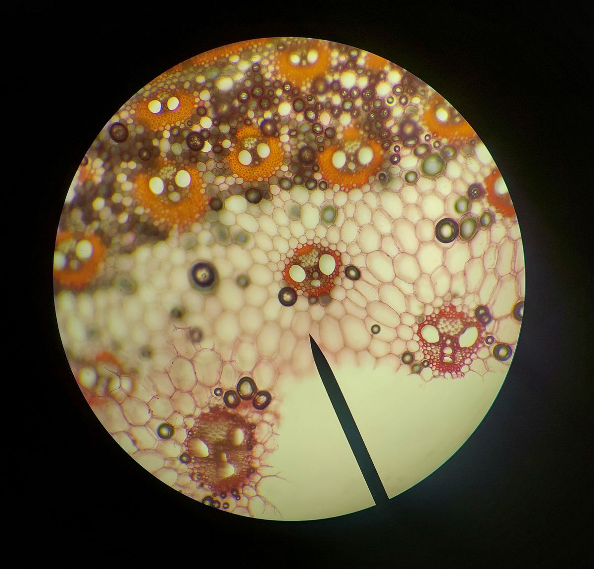
When a birefringent specimen is placed on the stage, it alters the polarisation of the light passing through it. Some of that altered light then passes through the analyser, producing an image. The colours and intensities in that image carry detailed information about the specimen's molecular order, crystal structure, orientation, and optical properties.
The technique is distinct from ordinary brightfield microscopy, which relies on differences in absorption or scattering. Polarized light microscopy reveals structure that would otherwise remain invisible, making it indispensable in geology, materials science, biology, and medicine.
For the fundamentals of polarised light itself, see our guide on what is polarised light. The polarisation concepts there — the rope-through-a-fence analogy, Malus's law, the three types of polarisation — are the foundation of everything described here.
How does a polarized light microscope work?
The working principle of polarized light microscopy follows a clear sequence:
- Unpolarised white light from the lamp passes through the polariser, becoming plane-polarised with its electric field vibrating in a single direction (typically East-West by convention).
- This polarised light passes through the condenser, which focuses it onto the specimen.
- If the specimen is birefringent, it splits the light into two orthogonal components called the ordinary and extraordinary rays. These travel at different speeds through the material (they experience different refractive indices).
- The two components emerge from the specimen with a phase difference — an optical path difference (OPD) — that depends on the specimen's thickness and birefringence.
- The analyser, oriented at 90° to the polariser, recombines these two components. Only light whose polarisation has been altered by the specimen passes through.
- The recombined components interfere — constructively for some wavelengths, destructively for others — producing the characteristic polarisation colours seen in the image.
The rotating stage is critical. As the specimen is rotated, its orientation relative to the polariser changes, and the brightness and colours cycle from zero (extinction) to maximum at 45° and back to zero at 90° of rotation. This cyclical behaviour is a hallmark of birefringent materials and helps distinguish them from isotropic substances.
For the physics of how light bends and slows when entering a medium, see our guide on how a lens works. The same refraction principles govern the behaviour of light in birefringent crystals.
Key components of a polarizing microscope
A dedicated polarising microscope includes several specialised components beyond those of a standard brightfield instrument:
| Component | Function |
|---|---|
| Polariser | Converts unpolarised light to plane-polarised light; positioned below the condenser, usually rotatable 360° |
| Analyser | Second polariser above the objective; oriented at 90° to the polariser (crossed position); can be slid in/out of the light path |
| Rotating stage | 360° circular stage with Vernier scale for precise angle measurement; critical for orientation studies |
| Strain-free objectives | Marked with P, PO, or Pol; built without internal stress that would produce unwanted birefringence |
| Bertrand lens | Auxiliary lens that projects the objective rear focal plane for observing conoscopic interference patterns |
| Compensator / retardation plates | Inserted between crossed polarisers to add or subtract OPD, enhancing contrast and enabling quantitative analysis |
| Centerable nosepiece | Allows each objective to be centred relative to the stage rotation axis |
| Cross-hair eyepiece | Eyepiece with reticle marking the centre of the field for orientation measurements |
The polariser and analyser are the heart of the system. Most modern instruments use synthetic dichroic film polarisers (Polaroid-type) rather than the traditional Nicol prisms of 19th-century petrographic microscopes. These film polarisers are compact, affordable, and provide excellent extinction when crossed.
Birefringence: the key to contrast
Birefringence — literally "double refraction" — is the physical property that makes polarized light microscopy possible. It occurs in materials that are anisotropic: their optical properties differ depending on the direction light travels through them.
In an isotropic material (glass, cubic crystals, liquids), the refractive index is the same in all directions. Light behaves the same way regardless of which way it enters. In an anisotropic material, the refractive index depends on the vibration direction of the light relative to the material's crystal axes.
The birefringence value is simply the numerical difference between the two refractive indices experienced by the ordinary and extraordinary rays. A material with high birefringence (like calcite, with a difference of about 0.172) produces strong interference colours at thin section thicknesses. A weakly birefringent material produces pale greys and whites.
The Michel-Lévy interference colour chart (or birefringence chart) maps the relationship between specimen thickness, birefringence, and the resulting interference colour. It is the standard reference for identifying materials from their appearance between crossed polarisers. At a standard thin section thickness of 30 micrometres, quartz (birefringence ~0.009) appears in first-order greys and whites, while calcite displays higher-order pastel colours.
The optical path difference (OPD) is calculated as:
OPD = t × Δn
Where t is the specimen thickness and Δn is the birefringence. When the OPD aligns with certain wavelengths of visible light, those wavelengths interfere destructively and are removed from the white light spectrum, producing the characteristic polarisation colours.

Applications of polarized light microscopy
Polarized light microscopy spans an extraordinary range of disciplines. Here are the major applications, each exploiting the technique's ability to reveal molecular order and structural detail.
Geology and mineralogy
This is the most traditional application. Geologists examine thin sections of rock — slices ground to 30 micrometres thick — between crossed polarisers to identify minerals, determine crystal orientation, and interpret the thermal and deformation history of the rock. Quartz, feldspar, mica, calcite, and olivine each produce characteristic interference colours and extinction angles that allow rapid identification.
The technique reveals features invisible in plain light: the twinning planes in plagioclase feldspar, the cleavage of amphiboles, and the undulose extinction that indicates strain in deformed quartz grains. Polarized light microscopy is the single most important tool in optical mineralogy, taught in every undergraduate geology programme worldwide.
Materials science
Engineers and materials scientists use polarised light to analyse stress in transparent materials (glass, plastics), examine polymer spherulite morphology, characterise liquid crystal phases, and inspect ceramic microstructures.
Stress birefringence is a particularly valuable application: glass or plastic under mechanical stress becomes birefringent, and the resulting interference pattern maps the stress distribution. This is used for quality control in glass manufacturing, plastic moulding, and optical component fabrication.
Polymer spherulites — radial crystal aggregates formed during cooling — appear between crossed polarisers as distinctive Maltese cross patterns with concentric banding. The size and distribution of spherulites provide information about the cooling rate and mechanical properties of the finished product.
Biology and medicine
Biological applications may be less widespread than geological ones, but they are no less important. Polarized light microscopy identifies:
- Gout crystals — monosodium urate crystals in synovial fluid show negative birefringence (yellow when aligned with the slow axis of a first-order red plate, blue when perpendicular). This is the definitive diagnostic test for gout.
- Amyloid deposits — Congo red-stained amyloid shows apple-green birefringence under crossed polarisers, a classic diagnostic finding in tissue pathology.
- Collagen — the highly ordered structure of collagen fibres produces strong birefringence, useful in studying connective tissue disorders.
- Starch grains — their radial organisation produces a characteristic Maltese cross extinction pattern.
- Cellulose and plant cell walls — the ordered cellulose microfibrils are birefringent, revealing the architecture of plant tissues.
For another microscopy technique that uses polarised light in a different way, see our guide on TIRF microscopy, which uses total internal reflection to create an evanescent wave for imaging cell surface dynamics.
Pharmaceutical and forensic science
Pharmaceutical analysis uses polarised light to characterise crystalline drug substances, identify polymorphs (different crystal forms of the same compound, which can have different bioavailability), and detect contamination. Forensic scientists use it to identify trace evidence such as fibres, paint fragments, and minerals.
Common misconception: "Polarised sunglasses work by being darker"
Many people think polarised sunglasses work because they are darker — the same way ordinary tinted glasses do. This is wrong.
Ordinary tinted lenses absorb all wavelengths equally. They reduce overall brightness but do not selectively remove glare. Polarised lenses work differently: they block light waves vibrating in a specific orientation (horizontal), while letting vertically vibrating light through. This kills the horizontal glare from roads, water, and car windscreens without darkening the rest of the scene as much.
This selective blocking of one polarisation orientation is the same principle at work in a polarising microscope. The polariser and analyser in the microscope are essentially doing what polarised sunglasses do — but with higher precision and the ability to rotate the elements to extract detailed information about the sample.
Extensions and related techniques
Polarized light microscopy forms the basis for several more advanced techniques:
Differential interference contrast (DIC) uses polarised light split into two laterally separated beams that recombine to produce a pseudo-3D image. It is one of the most powerful contrast methods for unstained biological specimens.
Conoscopy uses a Bertrand lens to observe the interference pattern at the objective rear focal plane, providing information about the optic sign and number of optical axes of crystals.
LC-PolScope is a modern quantitative variant that measures birefringence at every image point simultaneously, using liquid crystal variable retarders and computer-controlled polarisation analysis.
The Nikon MicroscopyU guide on polarised light microscopy provides an in-depth technical reference with detailed diagrams of the optical components and interference patterns. For a historical overview and further technical details, the Wikipedia article on polarised light microscopy covers the development from Brewster's and Talbot's early work to modern instruments.
The Leica Microsystems guide on the polarisation microscopy principle offers practical insights into alignment, component selection, and applications with high-quality example images.
Key takeaways
- Polarized light microscopy uses two crossed polarisers to generate contrast from birefringent materials.
- Birefringence is the splitting of light into two orthogonal components that travel at different speeds through anisotropic materials.
- The polariser converts unpolarised light to plane-polarised light; the analyser (crossed at 90°) recombines the split components.
- Interference colours reveal the specimen's structure, orientation, birefringence, and thickness.
- Applications span geology (mineral identification), materials science (stress analysis, polymers), biology (gout diagnosis, amyloid detection), and forensics.
- Strain-free objectives, a rotating stage, and compensator plates are essential components of a dedicated polarising microscope.
- Polarised sunglasses use the same principle — selective blocking of one polarisation orientation — not simply increased darkness.
Frequently Asked Questions
What is polarized light microscopy?
Polarized light microscopy is an optical microscopy technique that uses two crossed polarising filters — a polariser below the sample and an analyser above — to image birefringent (doubly-refracting) materials. It generates contrast through the interference of light waves split by the specimen's anisotropic structure, revealing details invisible in ordinary brightfield microscopy.
How does polarized light microscopy work?
A polariser converts unpolarised light into plane-polarised light before it reaches the specimen. If the specimen is birefringent, it splits the light into two orthogonal components (ordinary and extraordinary rays) that travel at different speeds. A second polariser (the analyser), oriented at 90° to the first, recombines these components, producing interference colours and contrast that map the specimen's structure and orientation.
What is birefringence in polarized light microscopy?
Birefringence, or double refraction, is the property of anisotropic materials to split light into two orthogonal wave components with different refractive indices. The numerical difference between these indices is the birefringence. It depends on both the material and the direction of light propagation. Birefringence is what makes a specimen visible between crossed polarisers.
What is the difference between polarizer and analyzer in a polarizing microscope?
The polariser is the first polarising filter, placed below the specimen stage, that converts unpolarised light into plane-polarised light. The analyser is the second polarising filter, placed above the objective, oriented at 90° to the polariser. When they are crossed in this way, no light reaches the eyepiece unless a birefringent specimen alters the polarisation of the light passing through it.
What are the applications of polarized light microscopy?
Polarized light microscopy is used extensively in geology and mineralogy for identifying minerals in rock thin sections, in materials science for analysing polymers, ceramics, and stress in glass, in biology for identifying crystals, amyloid, and cellulose, and in medicine for diagnosing gout by identifying monosodium urate crystals in synovial fluid.
What is the difference between polarized light microscopy and ordinary light microscopy?
Ordinary brightfield microscopy illuminates the specimen with unpolarised light and relies on absorption or scattering for contrast. Polarized light microscopy uses plane-polarised light and crossed polarisers to exploit birefringence, generating contrast based on the specimen's molecular order and crystalline structure rather than just its colour or opacity.
What specimens are examined with polarized light microscopy?
Specimens examined include minerals and rocks (in thin sections), crystals, polymers, textile fibres, asbestos, glass, ceramics, liquid crystals, biological structures such as starch grains, cellulose, collagen, amyloid, and gout crystals, as well as stressed plastics and industrial materials.
What is a first-order red plate in polarized light microscopy?
A first-order red plate (also called a full-wave or lambda plate) is a retardation plate with an optical path difference of about 550 nm. It is inserted between the crossed polarisers to add or subtract optical path difference from the specimen. This shifts the interference colours into the first-order red range, dramatically improving contrast for weakly birefringent materials and enabling determination of the slow and fast vibration directions.

About Umar Farooq
Umar Farooq writes in-depth guides on the physics of light and optics — from reflection, refraction, and lenses to diffraction, lasers, and fiber optics, explained from first principles.
Read more about Umar Farooq →