A ray diagram traces the path light takes through a lens or mirror so you can find the image without calculating anything. Draw two rays whose behaviour you already know, see where they cross, and that crossing point is the image. Its position tells you the image distance, its length tells you the size, and which way it points tells you whether the image is upright or inverted.
The useful thing is that the method does not change. Whether you are drawing light rays through a lens or ray diagrams for curved mirrors, the steps are identical — a concave mirror, a convex lens and a ray crossing into a block of glass are all drawn the same way. Only the rule for what each ray does when it meets the optic is different. Learn the four steps once and every diagram in the syllabus follows.
The parts of a ray diagram
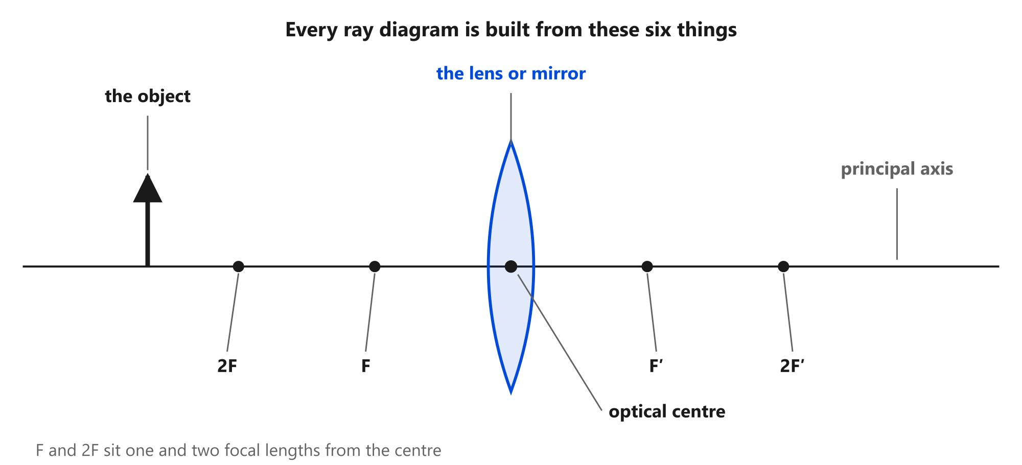
Every diagram is built from the same handful of pieces, and getting them on the page in the right order is most of the work.
The principal axis is the horizontal line the whole diagram is built on. It passes through the centre of the optic at right angles to it.
The optic — a lens or a mirror — sits on the axis. Draw a lens as a symmetrical shape at a single vertical line; draw a mirror as a curved arc.
The optical centre is the point where the axis meets the optic. For a mirror this is called the pole.
The focal point F sits one focal length from the centre, on both sides. 2F sits at twice that distance. Measure these properly — placing F by eye is the single most common reason a diagram comes out wrong.
The object is drawn as a vertical arrow standing on the axis, tail on the axis and tip above it. Every ray you draw starts from that tip.
The four steps
1. Set up the axis, the optic and the focal points. Use a ruler. Mark F and 2F on both sides at measured distances.
2. Stand the object on the axis as a vertical arrow at the given distance.
3. Send in two rays from the tip of the object — and here is the trick that makes the whole thing work. You do not pick rays at random. You pick the two rays whose behaviour you already know:
- the ray that arrives parallel to the axis
- the ray that goes through the centre, or through the focal point
4. Mark where the outgoing rays cross. Draw the image as an arrow from the axis to that crossing point.
That is the entire method. What changes between optics is only step 3.
Rule sheet: what each ray does
Lenses
| The ray that arrives… | leaves… |
|---|---|
| parallel to the axis | through the far focal point F′ |
| through the optical centre | unchanged, straight on |
| through the near focal point F | parallel to the axis |
Mirrors
| The ray that arrives… | leaves… |
|---|---|
| parallel to the axis | through the focal point F |
| through the focal point F | parallel to the axis |
| aimed at the centre of curvature C | straight back along itself |
Two rays are enough to fix the image, because two lines cross at one point. Drawing a third is how you check your work — all three should meet at the same place.
Worked: a concave mirror ray diagram
With the object beyond the centre of curvature, the parallel ray reflects through F and the ray through F reflects parallel. They cross in front of the mirror, so the image is real.
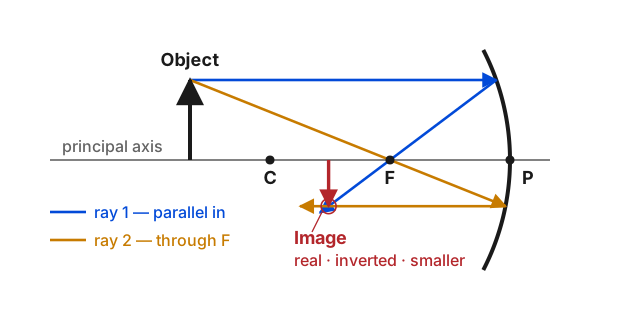
Full method for every object position: how to draw a concave mirror ray diagram.
Worked: a convex lens ray diagram
The same construction, with the lens rules instead. The parallel ray refracts through the far focal point, the central ray carries straight on, and they cross beyond F′.
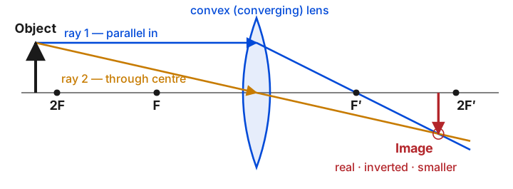
More on image formation at every position: convex lens.
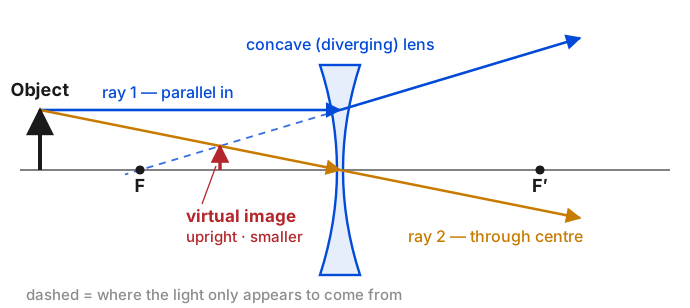
Worked: a concave lens ray diagram
A diverging lens is the case where the outgoing rays never meet. They spread apart, so you extend them backwards with dashed lines and find the image where those extensions cross.
Full guide: concave lens.
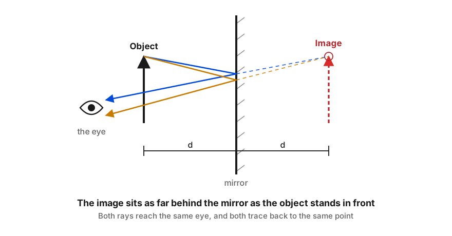
Worked: a plane mirror ray diagram
A flat mirror has no focal point, so the construction is simpler: reflect two rays off the surface and trace them back.
Full guide: plane mirror.
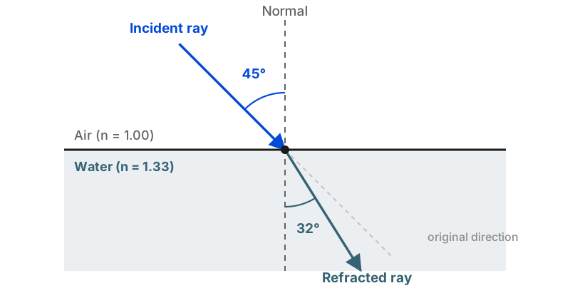
Worked: refraction at a boundary
Not every ray diagram involves a lens. When light crosses from one medium into another it bends at the surface, and the diagram needs a normal line rather than a focal point.
Full method: how to draw a refracted ray and how to draw a reflection diagram.
Real or virtual: how the diagram tells you
This is the part exam questions turn on, and the diagram answers it for you.
The outgoing rays themselves cross → the image is real. Draw it as a solid arrow. A screen placed there would catch a picture. Real images from a single optic are always inverted.
The outgoing rays spread apart, and only their backward extensions cross → the image is virtual. Draw it as a dashed arrow. No light ever reaches that point, so nothing can be projected there. Virtual images are always upright.
Plane mirrors, convex mirrors and diverging lenses can only ever produce the virtual kind. More on the distinction: real vs virtual image.
Getting the signs right
If you go on to check a diagram against the lens or mirror formula, the answer depends on measuring distances consistently.

Full reference: optics formulas cheat sheet.
Four mistakes that account for most wrong diagrams
Sending the wrong ray through F. Only the ray that arrived parallel to the axis leaves through the focal point. A ray that arrived at some other angle does not.
Placing F by eye. If F is not at a measured distance, nothing else in the diagram can be right. Measure it.
Drawing freehand. Rays are straight lines. A slight curve moves the crossing point and changes the answer.
Using solid lines for extensions. A backward extension is not a real light path. It gets a dashed line, and so does the virtual image it locates.
Checking your work
Draw a third ray using a rule you have not used yet. If all three cross at the same point, the diagram is correct. If one disagrees with the other two, that ray is the one drawn wrongly — go back and check which rule applies to it.
For a curved mirror, the third ray is usually the one aimed at the centre of curvature, which comes straight back along its own path. For a lens, use the ray through the near focal point, which leaves parallel to the axis.
Frequently Asked Questions
What is a ray diagram?
A ray diagram is a scale drawing that traces the path of light through an optical system using straight lines with arrows. By drawing two or three rays whose behaviour is known in advance, you can find where an image forms, how large it is, whether it is upright or inverted, and whether it is real or virtual — without doing any calculation.
How do you draw a ray diagram step by step?
Four steps. First draw the principal axis and place the optic on it, marking the focal point F and 2F on both sides. Second, draw the object as a vertical arrow standing on the axis. Third, send in two rays from the top of the object whose behaviour you already know — one parallel to the axis and one through the optical centre or focal point. Fourth, mark where the outgoing rays cross; that is the image.
How many rays do you need to draw a ray diagram?
Two are enough, because two straight lines cross at exactly one point. A third ray is worth drawing as a check — if all three meet at the same place, the diagram is right. If they do not, something has been drawn incorrectly.
What are the standard rays used in ray diagrams?
For a lens: a ray parallel to the axis refracts through the far focal point, a ray through the optical centre carries straight on, and a ray through the near focal point leaves parallel. For a mirror: a ray parallel to the axis reflects through F, a ray through F reflects parallel, and a ray aimed at the centre of curvature comes straight back.
How do you tell if the image in a ray diagram is real or virtual?
If the outgoing rays themselves cross, the image is real and is drawn with a solid arrow. If the outgoing rays spread apart and only their backward extensions cross, the image is virtual and is drawn with a dashed arrow. Real images are inverted; virtual images are upright.
Why do my rays not meet at one point?
Almost always one of three things: a ray has been reflected or refracted using the wrong rule, the focal point has been placed at the wrong distance, or the rays were drawn freehand rather than with a straight edge. Check the rule for each ray one at a time — the ray that disagrees with the other two is the one drawn wrongly.
Do you need to draw ray diagrams to scale?
For a rough answer about the type of image, no. For a numerical answer, yes — if the diagram is drawn to scale on squared paper, the image distance and image height can be read straight off the drawing and will agree with the lens or mirror formula to within a small error.

About Umar Farooq
Umar Farooq writes in-depth guides on the physics of light and optics — from reflection, refraction, and lenses to diffraction, lasers, and fiber optics, explained from first principles.
Read more about Umar Farooq →